
THE DIRECT ANSWER
Capacitance, inductance and resistance readings depend on frequency, stimulus level, bias, equivalent-circuit model and the fixture. Compare LCR results only after matching those conditions. A single plausible number, especially in circuit, does not establish that a component is healthy.
Record the conditions before the number
| Condition | What to record | Why it changes the result |
|---|---|---|
| Frequency and AC level | Actual selected frequency; voltage/current convention | Losses and impedance depend on frequency and stimulus. |
| DC bias and temperature | Bias arrangement, available temperature reading | Some dielectrics and magnetic cores change substantially. |
| Equivalent model | Series or parallel; reported C/L/R, ESR, D or Q | The same impedance can have different equivalent values. |
| Fixture and compensation | Lead geometry; open/short procedure and reference plane | Stray capacitance and series impedance are included otherwise. |
| Component state | Part marking; in/out of circuit; discharged state | Parallel paths and residual energy corrupt or endanger a test. |
The blank LCR record keeps these fields beside the reading. It deliberately contains no example measurements.
Prepare a safe, repeatable fixture
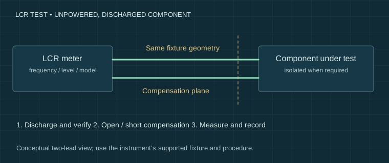
Disconnect power and discharge the component using an appropriate procedure; verify the absence of stored voltage before connecting an LCR meter. Do not discharge a capacitor through the meter. In-circuit tests include other paths, so isolate a lead or remove the component when the question requires its individual value.
- Choose the fixture appropriate to the instrument. A supported four-terminal-pair or Kelvin arrangement can reduce particular lead errors; ordinary clips do not acquire those properties by name.
- Perform the documented open and short compensation at the measurement plane. Keep lead spacing and geometry consistent with the test.
- Select a frequency and signal level compatible with the component specification and instrument range.
- Choose and record the series or parallel model; repeat after reseating to check contact sensitivity.
Compensation is not traceable calibration. If the meter provides no selectable level or bias, record that limitation rather than assuming another instrument’s setting.
ESR, DCR and capacitance answer different questions
ESR is an equivalent AC loss term at a stated frequency. DCR is a DC resistance measurement. Neither alone establishes capacitor leakage at operating voltage, insulation integrity or remaining service life. An in-circuit low ESR reading can belong to another capacitor in parallel.
For a simple series capacitor model, D = 2πfC × ESR and Q = 1 / D. These relations apply to that model at that frequency; do not mix a parallel-model capacitance with an unrelated ESR reading. Inductor core loss, saturation and self-resonance can also make a single low-level inductance value a poor predictor of operating behaviour.
When two meters disagree
First match frequency, level, model, bias and fixture. Compare against a stable component with a documented tolerance and, where needed, a calibrated reference or external calibration service. A disagreement is not automatically an error in the cheaper meter; both instruments may be measuring different conditions.
Save both readings with uncertainties or known limitations, and avoid “percentage accuracy” claims without a justified reference. Next use the measurement record method to separate the component observation from the diagnosis. The cited LCX200 review uses capabilities and equipment that a basic handheld meter may not provide.
Sources and their limits
These references support the principles described here. External tests remain the original authors’ work. Check the exact model manual before connecting equipment.
- Meettechniek — Measuring capacitance ↗Independent measurement methods and equivalent-circuit discussion.
- Meettechniek — Measuring inductance ↗Independent inductance measurement methods; results depend on the test conditions.
- Elliott Sound Products — ESR meters ↗ESR methods and limitations; includes simulations, which must not be read as measured waveforms.
- Gough’s Tech Zone — R&S LCX200: instrument performance ↗A specific instrument review and comparison, with the author’s equipment and disclosed review relationship. Not independent calibration of low-cost LCR meters.
Reviewed for this edition on 22 September 2026. How we use evidence →
Keep a record of the conditions.
Settings, circuit state and limitations belong with the reading. Our templates contain field headers only.
Measurement records & blank templates →