
THE PRACTICAL MEASUREMENT HANDBOOK
Understand
the waveform.
Trust the
measurement.
Clear guides to oscilloscopes, signal generators and LCR measurements. For the moment you need to know what a trace really means.
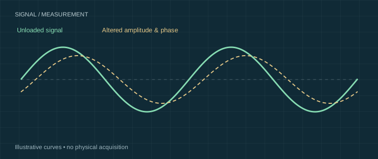
Understand the path that produced it.EXPLANATORY
ILLUSTRATION
THREE WAYS INTO THE BENCH
What are you working on?
Learning the basics
Connect safely. Set a useful timebase. Learn what the trace can—and cannot—tell you.
Start with acquisition ↗02 / YOUR NEXT MEASUREMENTFinding a fault
Turn a suspicious waveform into a testable question. Check the setup before replacing a part.
Follow the evidence ↗03 / YOUR NEXT MEASUREMENTDebugging embedded systems
Catch the right edge, keep its context and understand how probing changes your circuit.
Get the trigger right ↗GET THE FOUNDATIONS RIGHT
Better measurements start here.
Probe loading, compensation and ground leads
A probe becomes part of the circuit. Its resistance changes DC loading, its capacitance increasingly loads fast signals, and its ground lead can introduce ringing. Compensate a compatible passive probe, use a short return path and repeat the measurement before blaming the circuit.
Explore the guide Source-based guideOscilloscope grounding and input limits
Many bench oscilloscope probe ground clips, BNC shells and channel references connect to protective earth and to one another. Connecting a ground clip to a live node can short that node to earth. Battery power alone does not prove that a handheld scope has isolated inputs.
Explore the guide Source-based guideSignal generator amplitude and the load setting
A generator’s displayed amplitude may be specified for a selected load. With a 50 Ω source set to 1 Vpp into 50 Ω, a high-impedance input can see almost 2 Vpp. The load menu usually changes the amplitude convention; it does not necessarily change the physical output resistance.
Explore the guideBEFORE YOU PRESS RUN
A quick calculation.
A better question.
Plan the capture window, estimate probe loading or check that factor-of-two generator reading. See the formula and the limits behind every result.
Explore the calculators ↗- 01 / Record length
How much time fits in the memory? - 02 / Probe loading
How much can an ideal RC load change the signal? - 03 / Generator load
What voltage should reach the actual load?
KEEP THE CONDITIONS WITH THE CLAIM
Make the next measurement repeatable.
A number needs its setup. Keep the probe, input, sample rate, trigger and circuit state alongside the observation. Start with our blank measurement and LCR record templates.
Build a useful measurement record →Know what kind of evidence you’re reading.
This first edition publishes source-based guides, explanatory drawings and calculated examples. We have not yet published ScopeBench hardware tests. Automotive diagnostics is a separate application, outside this launch’s low-voltage core.
Our evidence method → Our retail relationship →