
THE DIRECT ANSWER
A probe becomes part of the circuit. Its resistance changes DC loading, its capacitance increasingly loads fast signals, and its ground lead can introduce ringing. Compensate a compatible passive probe, use a short return path and repeat the measurement before blaming the circuit.
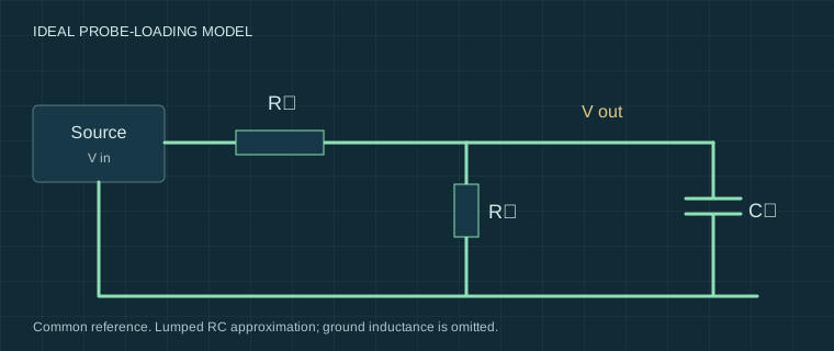
Why a high-resistance probe still changes an edge
For a first approximation, model the circuit as an ideal voltage source with resistance Rₛ, feeding the probe resistance Rₚ in parallel with capacitance Cₚ. This gives H(f) = 1 / (1 + Rₛ/Rₚ + j2πfRₛCₚ). At DC only the resistive divider remains. At higher frequencies the capacitance reduces amplitude and introduces phase lag.
As a calculated example, Rₛ = 10 kΩ, Rₚ = 10 MΩ and Cₚ = 12 pF give about 0.798 amplitude ratio and −37.0° phase at 1 MHz. These are illustrative values, not measurements or typical specifications promised for every 10× probe. Try the probe-loading calculator with your documented values.
The model excludes ground-lead inductance, distributed transmission-line effects and the full probe/scope response. It will not predict all observed ringing.
Compensate the probe for the input you use
- Check probe voltage rating, attenuation and scope input compatibility. A conventional compensated 10× passive probe normally expects a specified 1 MΩ input and capacitance range.
- Connect the probe to the scope’s documented compensation output and reference terminal. Set both the probe switch and scope channel factor to 10×.
- Adjust the probe’s low-frequency compensation as its manual describes. Aim for the specified square-wave shape, without rounded or peaked tops.
- Recheck after changing scope input or probe. Save the input and probe settings with important captures.
Compensation corrects a divider match. It does not calibrate the whole measurement system or prove high-frequency accuracy. Do not switch the scope to 50 Ω with a standard 10× probe unless that combination is explicitly supported.
Separate circuit ringing from the measurement loop
On a safe low-voltage source, compare the same edge with a long ground clip and a short ground spring supported by the probe. Keep the probe tip location, bandwidth setting and signal unchanged. A large change in ringing when only the return path changes is evidence that the measurement arrangement contributes to the trace.
Record the length and route of both connections, the source edge rate and the probe model. A slower source cannot reveal every limitation of a fast probe; a faster scope may be needed to characterise the measurement system itself. Never move the ground connection to a different-potential node just to obtain a cleaner display.
Common mistakes and the next check
A 1× probe setting often has substantially more capacitance and less bandwidth than 10×; use its actual manual values. Probe-factor mismatch produces a scale error even if the trace looks plausible. An unstable oscillator may stop because of loading, so “no signal” can be caused by the act of probing.
Next, compare a lower-capacitance measurement method where appropriate, shorten the reference connection and repeat. If the result changes, report both arrangements. Read the grounding and input-limit guide before connecting a second instrument.
Sources and their limits
These references support the principles described here. External tests remain the original authors’ work. Check the exact model manual before connecting equipment.
- Meettechniek — Oscilloscope probes ↗Independent explanation and experiments on probe loading and compensation; the author’s equipment and conditions apply.
- Tektronix — XYZs of Oscilloscopes primer ↗Manufacturer primer: acquisition, triggering, probes and measurement systems; not a test of our instruments.
- Teledyne LeCroy — Oscilloscopes: 50 ohm input and 1 Mohm input ↗Manufacturer explanation of termination and input arrangements; consult the exact instrument manual for limits.
Reviewed for this edition on 22 September 2026. How we use evidence →
Keep a record of the conditions.
Settings, circuit state and limitations belong with the reading. Our templates contain field headers only.
Measurement records & blank templates →