
THE DIRECT ANSWER
Many bench oscilloscope probe ground clips, BNC shells and channel references connect to protective earth and to one another. Connecting a ground clip to a live node can short that node to earth. Battery power alone does not prove that a handheld scope has isolated inputs.
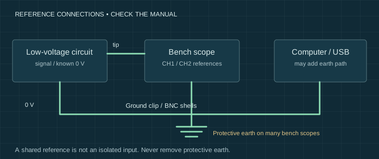
Map the reference path before connecting
Start with the exact instrument and probe manuals. Establish whether channel references are common, whether they connect to protective earth, and whether a USB lead, charger, generator or computer adds another path. A battery-operated instrument can have common channel grounds even when it floats relative to earth.
Our diagrams and exercises concern ordinary low-voltage circuits with a known reference. They do not authorise measurements on mains wiring, switch-mode supply primary circuits, traction batteries or ignition systems. Automotive diagnosis is an adjacent discipline with different transient and connection requirements.
- With power off, identify the intended signal reference and all attached instruments.
- Confirm the maximum signal, offset, common-mode voltage and expected transients.
- Check ratings for the whole probe/input combination and the selected mode.
- Connect only when the reference arrangement and limits are understood.
Input range, voltage rating and bandwidth are different
| Item | Why it matters |
|---|---|
| Displayed volts/div | Controls the display scale; it does not establish a safe maximum input. |
| DC plus peak AC rating | Offset and waveform peaks both matter. Check frequency derating. |
| 1 MΩ or 50 Ω input | Changes loading and often permitted voltage/power substantially. |
| Probe and accessories | The lowest applicable rating limits the arrangement. |
| Common-mode and isolation ratings | Define permitted voltage relative to earth or between isolated channels. |
AC coupling removes a DC component from the displayed path; it does not make an unsafe connection safe. A 10× setting in a menu does not add physical attenuation or insulation. A CAT rating, where specified, concerns a defined measurement environment and cannot be inferred from a peak-voltage advertisement.
Measure between two nodes with the right method
A correctly rated differential probe or a documented isolated-input instrument may support a measurement between two non-earth nodes. Check both differential and common-mode limits, frequency derating and permitted accessories. “Handheld”, “USB” and “battery powered” are not substitutes for that specification.
Two conventional channels with mathematical subtraction still have common grounded inputs. Both probe ground clips must remain on a compatible common reference, and each input must remain within its own limits. Subtraction does not create galvanic isolation; channel mismatch also limits rejection of a shared signal.
Never remove protective earth from a bench oscilloscope to float its case. Do not treat an isolation transformer as a blanket solution to probe or input safety.
If the circuit changes when connected
Stop and investigate an unexpected current, reset, spark or altered supply reading; do not continue by moving ground clips at random. Reconstruct all reference paths, including USB and the generator output. For a safe low-voltage circuit, document the power arrangement before repeating the measurement.
Next check loading and ground-lead effects if the electrical reference is sound but the waveform shape changes. A tidy trace alone is not evidence of a safe or valid connection.
Sources and their limits
These references support the principles described here. External tests remain the original authors’ work. Check the exact model manual before connecting equipment.
- Tektronix — XYZs of Oscilloscopes primer ↗Manufacturer primer: acquisition, triggering, probes and measurement systems; not a test of our instruments.
- Elliott Sound Products — Oscilloscopes ↗Independent practical discussion of scope operation and measurement limitations.
- Teledyne LeCroy — Oscilloscopes: 50 ohm input and 1 Mohm input ↗Manufacturer explanation of termination and input arrangements; consult the exact instrument manual for limits.
Reviewed for this edition on 22 September 2026. How we use evidence →
Keep a record of the conditions.
Settings, circuit state and limitations belong with the reading. Our templates contain field headers only.
Measurement records & blank templates →