
THE DIRECT ANSWER
A generator’s displayed amplitude may be specified for a selected load. With a 50 Ω source set to 1 Vpp into 50 Ω, a high-impedance input can see almost 2 Vpp. The load menu usually changes the amplitude convention; it does not necessarily change the physical output resistance.
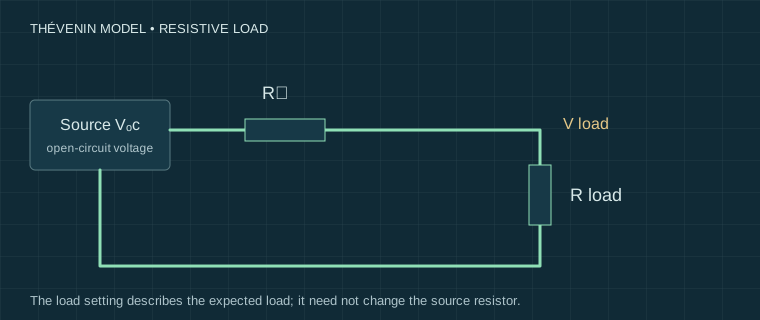
Use the source-plus-resistor model
Represent the output by an open-circuit voltage Vₒc in series with resistance Rₛ. With a resistive load Rₗ, the expected voltage is Vₗ = Vₒc × Rₗ / (Rₛ + Rₗ). If Vset is specified into Rset, then Vₒc = Vset × (Rₛ + Rset) / Rset. For a high-impedance setting, the model uses Vₒc = Vset.
These equations describe an ideal linear resistive source, not a calibration. The generator-load calculator exposes both the selected load and the actual load so that a plausible factor-of-two error is easy to recognise.
| Setting, with 50 Ω source | Actual load | Calculated Vpp |
|---|---|---|
| 1 Vpp into 50 Ω | 50 Ω | 1 Vpp |
| 1 Vpp into 50 Ω | 1 MΩ | 1.9999 Vpp |
| 1 Vpp, High-Z | 50 Ω | 0.5 Vpp |
Connect and record a controlled comparison
Use a low-amplitude, low-frequency sine wave and zero offset to start. Confirm that the scope and generator share a compatible reference. With output disabled, connect the documented cable/termination arrangement. Record whether the scope input is 1 MΩ or 50 Ω and whether an external terminator is present.
- Read the generator’s source impedance and load-setting convention in its manual.
- Set a modest amplitude, frequency and offset, then enable the output.
- Record the measured Vpp and the generator’s amplitude units. Vpp, peak and RMS are not interchangeable.
- If a second load is suitable and rated for the power, disable output, change the load and repeat.
For a sine wave without clipping, Vrms = Vpp / (2√2). Other waveform shapes need their own conversion. A DC offset adds to the peak voltage and can exhaust the output’s allowed range.
Why the real result may differ
The calculator omits output current limits, clipping, offset-dependent amplitude limits, cable reflections and frequency-dependent impedance. A scope’s 1 MΩ input has capacitance; it is not a perfect open circuit at high frequency. A 50 Ω terminator has a finite power and frequency rating. Its dissipation is P = Vrms² / R for the voltage actually across it.
A long cable carrying a fast edge is a transmission line. Matching and measurement location matter; a simple resistive divider cannot predict overshoot or reflections. Conversely, adding 50 Ω to a weak circuit node can heavily load it. A terminator is not a universal remedy for a messy trace.
Before calling the generator inaccurate
Check probe factor, amplitude units, selected versus actual load and whether the waveform is clipped. Reduce amplitude and frequency, remove unintended parallel loads, then repeat. Record the firmware and mode of a combination instrument: generator operation may change scope acquisition or share its reference.
Next review three-in-one trade-offs. Comparing a device’s generator with its own scope can find gross problems, but shared references and errors prevent that from being independent calibration.
Sources and their limits
These references support the principles described here. External tests remain the original authors’ work. Check the exact model manual before connecting equipment.
- Tektronix — Why is the measured AFG/AWG amplitude double the setting? ↗Manufacturer FAQ 57426: a 50 Ω source, matched-load voltage and higher-impedance loads. Our calculator generalises the stated resistive divider; verify the load-setting convention in your model manual.
- Teledyne LeCroy — Oscilloscopes: 50 ohm input and 1 Mohm input ↗Manufacturer explanation of termination and input arrangements; consult the exact instrument manual for limits.
- Teledyne LeCroy — Is it OK to use an external 50 ohm termination? ↗Termination bandwidth and power limitations; not permission to terminate an arbitrary circuit in 50 ohms.
- Elliott Sound Products — Oscilloscopes ↗Independent practical discussion of scope operation and measurement limitations.
Reviewed for this edition on 22 September 2026. How we use evidence →
Keep a record of the conditions.
Settings, circuit state and limitations belong with the reading. Our templates contain field headers only.
Measurement records & blank templates →