
THE DIRECT ANSWER
An oscilloscope, multimeter and generator in one case can be convenient, but three named functions do not imply three independent instruments. Check which modes run together, whether references are shared, what changes during switching, and whether the data you need can be exported.
The questions a specification table should answer
| Question | Why it matters |
|---|---|
| Can scope and generator run simultaneously? | Some functions may share processing, controls or connectors. |
| What happens to rate and memory? | A maximum specification may apply only in one mode. |
| Which terminals share a reference? | Generator, scope, meter and USB paths can change the circuit connection. |
| Does switching require moving leads? | A lead in a current input is not safe for an ordinary voltage connection. |
| What can be saved? | Raw waveform export, screenshots and meter logs are different evidence. |
| What limits apply in each function? | One function’s voltage or CAT rating does not automatically cover another. |
Plan the connections before changing mode
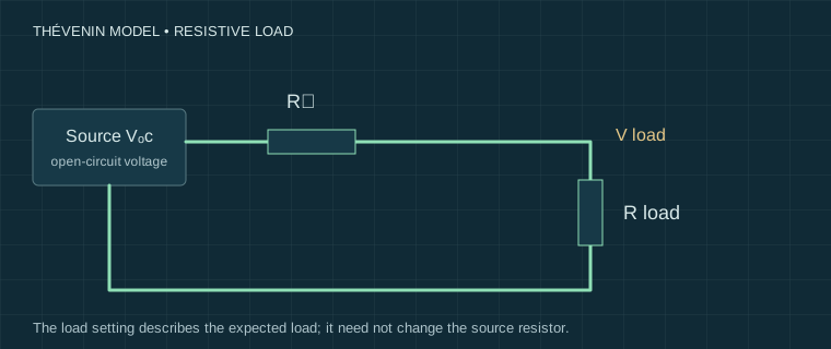
For a safe low-voltage exercise, draw the generator output through its source impedance to the circuit input, and the scope input at the circuit output. Mark every reference, including a connected computer. The schematic illustrates the required reasoning; it is not a wiring approval for an unspecified combination product.
Follow the manual’s sequence for stopping output, disconnecting and moving leads. Check whether switching modes retains generator output or changes range and coupling. A mode label alone does not tell you the terminal protection or internal connection.
Self-checking is not independent calibration
Looping the built-in generator into the built-in scope can demonstrate basic operation and expose a gross scale or load-setting mistake. It cannot independently establish accuracy if both functions share a clock, reference or systematic error. A second inexpensive instrument is also not automatically a calibrated reference.
For acquisition checks, generate a documented low-voltage pulse sequence, save the entire record and compare timestamps and event counts. For amplitude claims, use a reference with known applicable uncertainty and sufficient bandwidth. Record the reference and limitations alongside any comparison; do not convert a plausible trace into a claimed accuracy percentage.
When the convenience is worthwhile
A combination unit may suit introductory experiments, portable low-voltage checks or tasks that use one function at a time. Simultaneous multi-channel debugging, rare-event capture and repeatable exports may justify separate instruments. Decide from the exact task and documented model capability.
RIGOL, FNIRSI and Hantek names cover different products; no family-wide performance conclusion follows from a retail listing. These pages contain no hands-on model verdicts. Next use the generator load guide and log the modes in a measurement record.
Sources and their limits
These references support the principles described here. External tests remain the original authors’ work. Check the exact model manual before connecting equipment.
- Tektronix — XYZs of Oscilloscopes primer ↗Manufacturer primer: acquisition, triggering, probes and measurement systems; not a ScopeBench measurement.
- Teledyne LeCroy — Oscilloscopes: 50 ohm input and 1 Mohm input ↗Manufacturer explanation of termination and input arrangements; consult the exact instrument manual for limits.
- Elliott Sound Products — Oscilloscopes ↗Independent practical discussion of scope operation and measurement limitations.
Reviewed for this edition on 22 September 2026. How we use evidence →
Keep a record of the conditions.
Settings, circuit state and limitations belong with the reading. Our templates contain field headers only.
Measurement records & blank templates →