
THE DIRECT ANSWER
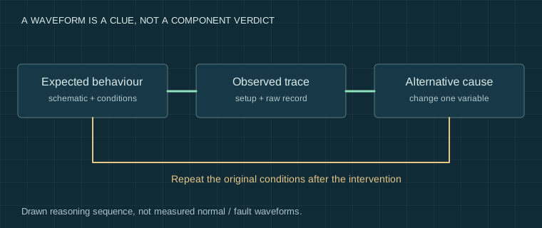
A waveform is evidence about a circuit under stated conditions, not a verdict on a component. Define the expected signal, capture the operating state and test an alternative explanation. A reference trace is useful only when load, supply, timing and measurement setup are comparable.
Start with a question the circuit can answer
For learning, ask whether a simple RC network follows the predicted charging curve. For repair, ask whether a low-voltage rail sags when the load starts. For embedded debugging, ask whether reset, clock or a serial transition occurs in the expected order. These questions need different time windows and trigger conditions.
Our sketches are explanatory illustrations, not captures from working or faulty products. This first edition does not contain a measured “known-good” waveform library. Automotive traces belong to a separate application: engine state, sensor type, test equipment and transient exposure must all be considered.
Useful observations and competing explanations
| Observation | Possible circuit explanation | Check the measurement first |
|---|---|---|
| Ringing on a digital edge | Interconnect or termination behaviour | Ground-loop length, probe compensation, bandwidth |
| Supply ripple or dips | Load step, regulation or filtering problem | Probe return, AC/DC coupling, time window, bandwidth limit |
| A clock seems slow or intermittent | Clock gating, resets or oscillator instability | Aliasing, trigger mode, dead time, probe loading |
| Serial decode errors | Timing, framing or signal-level problem | Threshold, bit rate, polarity, sample rate, grounding |
These are hypotheses, not component diagnoses. A trace that resembles a published failure can have a different cause.
A low-voltage fault-finding sequence
- Write the expected behaviour from the schematic, timing specification or a genuinely comparable working unit.
- Document supply, load, firmware and operating state. Identify a safe reference before connecting.
- Capture the symptom with a suitable trigger and enough pre-event context. Include a second channel for a suspected cause where useful.
- Change one variable: shorten the probe return, substitute a known load, or repeat with the same firmware state.
- Retest under the original fault-producing conditions after any intervention.
For example, a reset coinciding with a rail dip is a correlation. Check their relative timing and the device’s reset/brownout requirements before concluding that the supply caused it. A narrow glitch that falls outside the sampled or armed interval can be missed.
Keep the evidence someone else would need
Save the raw acquisition if the scope supports it, together with a readable screen image, schematic and settings. Record model, firmware, probes, channel factor, coupling, termination, timebase, actual sample rate, memory, trigger and acquisition mode. Include a negative result or an alternative cause that was ruled out, with the scope of that check.
The blank measurement record is designed for this workflow. Mark an uncertainty as unknown rather than inventing a number. If only a screenshot survives, say that numerical re-analysis may be limited. A before/after trace supports a repair only if the conditions and original symptom have been repeated.
Sources and their limits
These references support the principles described here. External tests remain the original authors’ work. Check the exact model manual before connecting equipment.
- Elliott Sound Products — Troubleshooting and repair ↗Practical diagnostic reasoning; broader repair topics exceed this site’s low-voltage scope.
- Tektronix — XYZs of Oscilloscopes primer ↗Manufacturer primer: acquisition, triggering, probes and measurement systems; not a test of our instruments.
- Meettechniek — Oscilloscope probes ↗Independent explanation and experiments on probe loading and compensation; the author’s equipment and conditions apply.
Reviewed for this edition on 22 September 2026. How we use evidence →
Keep a record of the conditions.
Settings, circuit state and limitations belong with the reading. Our templates contain field headers only.
Measurement records & blank templates →