
THE DIRECT ANSWER
Bandwidth limits the analogue signal that reaches the converter. Sample rate sets the spacing of captured points. Record length sets how long that rate can be maintained. Check all three in the channel and acquisition mode you will actually use.
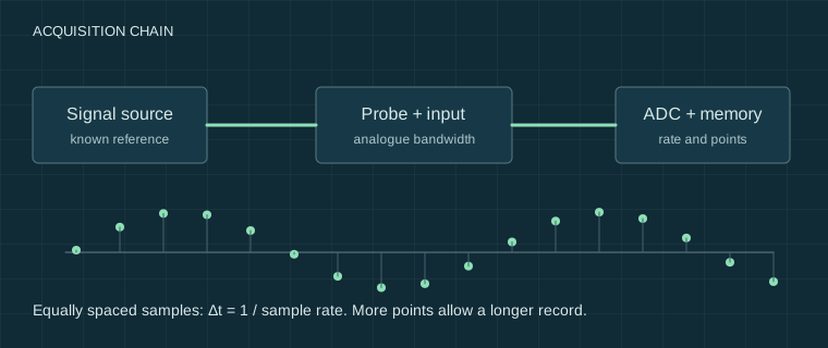
Three specifications, three different questions
A 100 MHz bandwidth label does not promise a faithful 100 MHz square wave. Bandwidth usually describes a small-signal sine response down by 3 dB: roughly 0.707 of the low-frequency amplitude at the stated limit. Fast edges contain higher-frequency components, so their shape can change well below that nominal limit.
| Specification | What it answers | What to check |
|---|---|---|
| Analogue bandwidth | Which frequency components reach the ADC? | Probe, input impedance, coupling, bandwidth limit |
| Actual sample rate | How far apart are recorded points? | Active channels, timebase, acquisition mode |
| Points per channel | How much time fits in one capture? | Memory allocation, export length, pre-trigger share |
The familiar relation rise time ≈ 0.35 / bandwidth is an approximation for particular response shapes. A generator, probe and oscilloscope all contribute to a measured edge. Measuring their combined rise time does not independently verify the scope’s bandwidth.
Set a capture window before choosing a sample rate
For an illustrative 10 ms transaction, 100 MS/s requires one million points per channel. The nominal window is T = N / fₛ; the time between the first and last of N equally spaced samples is (N − 1) / fₛ. Use the record-length calculator to plan a window, then read the actual rate on the instrument.
Enabling a second or fourth channel can reduce the available sample rate or memory on some instruments. A longer timebase may also reduce the rate. Digital interpolation makes a trace look smooth but does not add independently captured information. A screen image may contain far fewer pixels than the acquisition has samples.
Nyquist’s greater-than-twice-frequency condition assumes a band-limited signal and suitable reconstruction. It is not a useful blanket promise of edge fidelity with two points per cycle. Use more points across the fastest feature you need, and test that the conclusion survives a change of timebase.
A reproducible low-voltage setup
Connect a generator through a compatible lead or probe to one scope channel, with both references on the same safe circuit 0 V. Check the generator load setting and scope termination before enabling output. Start with a modest low-frequency sine wave; record its frequency, amplitude, offset and the input settings.
- Save a capture with the sample rate and point count visible.
- Lengthen the time window, note whether the rate drops, then zoom the stored record.
- Repeat with another channel enabled. Keep the input signal unchanged.
- Try a pulse train and compare whether short pulses remain captured. Save raw points when supported.
This establishes acquisition behaviour for that setup, not calibrated bandwidth. Testing hundreds of megahertz needs a suitable source, fixtures and reference path.
Common misreadings and the next check
A slow-looking waveform can be an alias. A missing glitch can fall between acquisitions or between samples. Peak-detect, averaging and high-resolution modes change what the stored data represent; equivalent-time sampling is unsuitable for an unrepeated transient. Record these modes rather than quoting the maximum sample rate from a listing.
Next, use a deliberate trigger and repeat the acquisition at a faster actual rate. If the event still disappears, check dead time, threshold and pulse width before declaring the circuit fault-free.
Sources and their limits
These references support the principles described here. External tests remain the original authors’ work. Check the exact model manual before connecting equipment.
- Tektronix — XYZs of Oscilloscopes primer ↗Manufacturer primer: acquisition, triggering, probes and measurement systems; not a test of our instruments.
- Gough’s Tech Zone — Capturing VGA frames with an oscilloscope ↗An external acquisition case illustrating memory, sampling and processing requirements; not a ScopeBench experiment.
Reviewed for this edition on 22 September 2026. How we use evidence →
Keep a record of the conditions.
Settings, circuit state and limitations belong with the reading. Our templates contain field headers only.
Measurement records & blank templates →